power flame burner wiring diagram
Patent Number 6508645 The X4 family of small gas burners has the capability of firing against a positive. Charger hp diagram hstnn ca15 circuit.

Experimental Set Up For Measurement Of Breakdown Electric Field Download High Resolution Scientific Diagram
Click here for the Power Flame library.

. Wiring and gas andor oil piping diagrams are furnished with each burner in accordance with individual job or application requirements. Cmax Manual Rev 0217 A. The two power leads black and white are located inside the burner panel.
Burner Director Management Boiler Burners Power Flame. 61 Refer to wiring diagram shipped with burner and typical wiring diagrams Figures 5 and 5A. The two power leads black and white are located inside the burner panel.
If supplied 62 Electrical installation must be made in accordance with National Electrical Code and applicable local codes. Flame safeguard control safety switch tripped out. General 211 Before beginning installation carefully study these.
Comprehensive wiring diagrams are furnished with each burner. Wall mounted or free-standing control panels are. Special panels for wall mounting or free standing.
Tighten all terminal screws and consult. 61 Refer to wiring diagram shipped with burner and typical wiring diagrams Figures 5 and 5A. 14 Pics about Diagram together with GM HEI Ignition Module Wiring Diagram.
Reset and determine cause for apparent flame failure. 62Electrical installation must be made in accordance with the NEC NFPA 70 or Canadian Electrical Code Part 1 and applicable. Wiring and gas andor oil piping diagrams are furnished with each burner in accordance with individual job or application requirements.
Panels and burners are fire tested before shipment. We manufacture a wide range of commercial burners industrial burners boiler burners. Figure 4 C Lr Internal Wiring Diagram End Vent Burner Manualzz.
INSTALLATION 21 Burner Mounting. Wall mounted or free-standing control panels are. 6 WIRING 61 Refer to wiring diagram shipped with burner.
Each Power Flame VECTOR burner is factory test fired to ensure that components and systems are functional. Atwood Furnace Wiring Diagram. Because each field application is unique the final burner set-up.
FD FDM Installation Operation Manual - POWER FLAME INCORPORATED 6 2. Loose connections or faulty wiring. Power Flames Extreme Small Gas Burner 400000-725000 BTUHR.
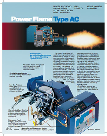
Power flame wiring diagram Diagram together with GM HEI Ignition Module Wiring Diagram. Type C Burners are designed to fire a wide range of gaseous as well as 2 or similar distillate fuels. Packaged Liquid Waste Fuel Burning systems employing the basic design.
WIRING 61 Refer to wiring diagram shipped with burner.

Classification Of Pulverized Coal Burners

Gas Burner Primary Control Heater Service Troubleshooting

I Have A Burnham Boiler With A Power Flame C2 G Burner And It Will Not Start The Burner Until The Fluid Temperature
![]()
Fireye Flame Safeguard And Combustion Controls
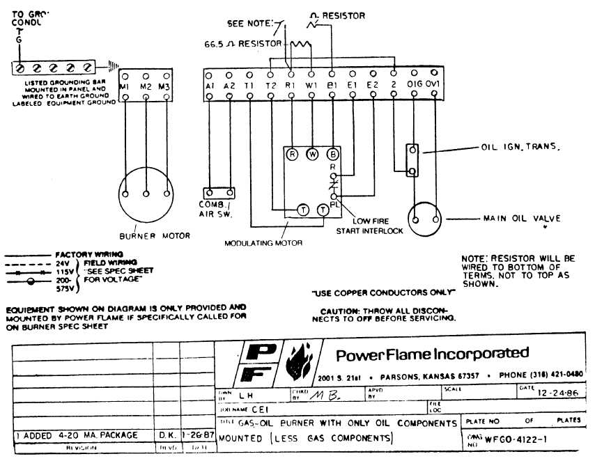
Gas Oil Burner With Only Oil Components Mounted Less Gas Components
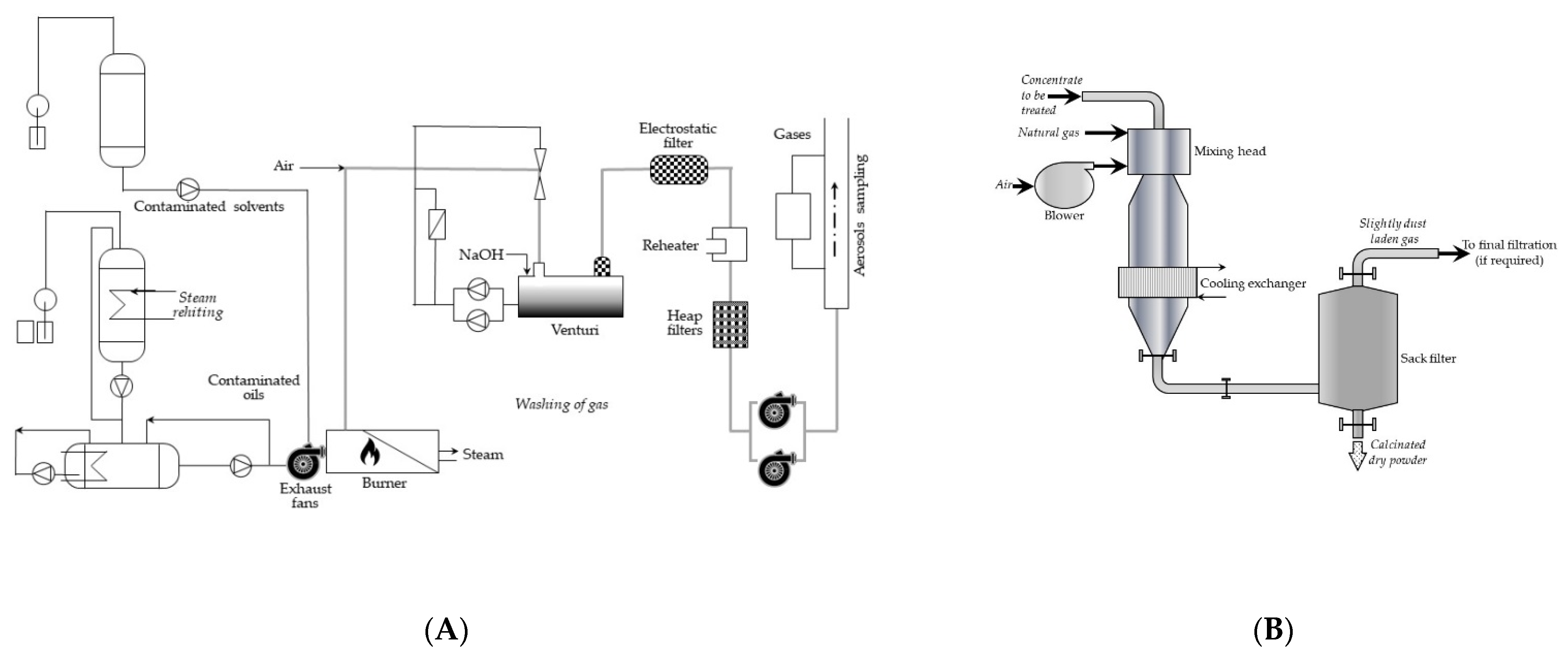
Energies Free Full Text Methods Of Thermal Treatment Of Radioactive Waste Html

Simultaneous Two Phase Flame Velocity Measurement Using Laser Induced Incandescence Particle Image Velocimetry Lii Piv Sciencedirect
Industrial Burners In Ohio Kentucky And Indiana Lathrop Trotter

West Auctions Auction Online Tenant Abandonment Auction In San Pablo Ca Item Power Flame Burner Model J30a 10 And Zhongda No 99071503

Power Flame C1 Go 12 Manuals Manualslib

Energy Management Of Renewable Energy Based Combined Heat And Power Systems A Review Sciencedirect
Wiring Diagrams Royal Series Royal Range Of California

Articles
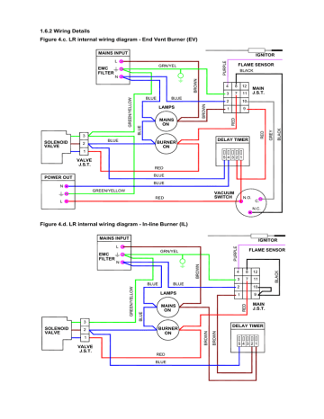
Figure 4 C Lr Internal Wiring Diagram End Vent Burner Manualzz

10 Tips For Safeguarding Combustion Processes Process Heating
Oil Burner Manuals Download Free Oil Burner Manuals All Brands

Powerflame J Burner Manualzz